Using the LPC1114 for sound input and output
The LPC1114 does not have a DAC so it might seem that it is not possible
to generate a sound (analogue) output. However, its PWM system can be run
fast enough to generate acceptable sound. This example uses a timer/counter
to generate a PWM output with a switching speed of 48MHz/1024 or 46875 Hz.
This is more than twice the highest frequency humans can typically hear so
it should be sufficient for audio. At this frequency the PWM system has a
resolution of 10 bits (hence the 1024 above). This matches the ADC resolution.
The example runs the ADC and PWM system at the same frequency. At the end of
each PWM cycle, the PWM duty is simply set equal to the value returned by the
ADC. The net result is that audio is simply passed through the system unchanged.
The analogue interface on the input to the ADC simply consists of a leve shift to
half the supply voltage and a unity gain buffer. This was deemed necessary as
the high impedance of the level shift network was leading to voltage drops during
the ADC's sample and hold phase. The op-amp is an OPA2336 which behaves well at
3.3V and is almost "rail-to-rail" capable.
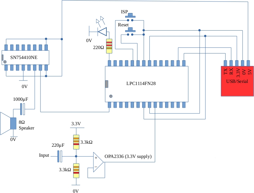
The output interface consists of an SN754410 H-Bridge chip (only one output is used)
driving a speaker via a large capacitor (note the polarity: negative to the speaker)
which removes the average DC level.
Performance
The system can pass analogue inputs of up to 1V peak to peak amplitude with a frequency
up to about 20kHz and down to a few tens of Hz. The output "sounds" ok generally (not
very scientific but time did not permit a thorough assessment). Some modulation
distortion (tones) is noticeable at certain frequencies perhaps from the sidebands either side
of the switching frequency.
Code is available here. Mail me if you have trouble compiling etc.
and be careful with those capacitor polarities!
Back to LPC1114 home