Interfacing the MPU6050 accelerometer/gyro with the LPC1114
The example code here controls an MPU6050 module over the I2C bus. The module was bought for a few Euro in dx.com . It connects to the
LPC1114 as shown here.
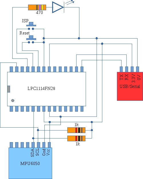 The MPU6050 module incorporates a 3-axis accelerometer, a 3-axis gyroscope and a temperature sensor. The demonstration
program reads all of these values and dumps them to the serial port. The I2C interface to the LPC1114 operates at
400kHz and the code followed the LPC1114 user manual's state machine approach (see section 15.11 in UM10398). This introduced
an element of asycnchronism to the code which took a little getting used to. In an effort to unravel what was happening
a "state-recorder" was used where the LPC1114's I2C status register was pushed into an array that allowed post-run analysis
to be carried out. The code for this state-recorder is shown below and is included in the project archive which
can be downloaded here.
The MPU6050 module incorporates a 3-axis accelerometer, a 3-axis gyroscope and a temperature sensor. The demonstration
program reads all of these values and dumps them to the serial port. The I2C interface to the LPC1114 operates at
400kHz and the code followed the LPC1114 user manual's state machine approach (see section 15.11 in UM10398). This introduced
an element of asycnchronism to the code which took a little getting used to. In an effort to unravel what was happening
a "state-recorder" was used where the LPC1114's I2C status register was pushed into an array that allowed post-run analysis
to be carried out. The code for this state-recorder is shown below and is included in the project archive which
can be downloaded here.
The LPC1114 was programmed using ISP/IAP over a serial port. An LED was also included to help with diagnostics.
#define MAX_TRACE 20
int debug_trace_data[MAX_TRACE];
volatile int debug_count=0;
void debug_trace(int value)
{
	if (debug_count < MAX_TRACE)
		debug_trace_data[debug_count++]=value;
}
void dump_debug_trace()
{
	int i=0;
	while (i < MAX_TRACE)
	{
		printByte(debug_trace_data[i++]);
		printString(" ");
	}
}
void reset_debug_trace()
{
	int i=0;
	while(i < MAX_TRACE)
	{
		debug_trace_data[i++]=0;
	}
	debug_count = 0;
}
Back to LPC1114 home