Introduction
I wanted to experiment with the NRF24L01+ radio from Nordic Semiconductor as it seemed to offer very low cost
and very low energy radio communications for embedded systems. You can buy a pair of modules for about 4 Euro
if you shop around. They claim to have a range of up to 80m and can support data rates of up to 2Mbps. More
technical details can be found at the Nordic semiconductor website.
The modules I used were bought in dx.com.
Of course these modules need to be used in conjunction with some sort of host processor. This little
project uses the LPC1114FN28 chip from NXP on one end and an Intel Galileo 2 board on the other.
Software development
I spent quite a while going through and trying various online libraries for the NRF24L01 to varying degrees of
success. There are plenty of Arduino and AVR tutorials and also some for MSP430's and ARMs. There are fewer
examples for the Intel Galileo 2 however which led me to the decision that I should write my own interface
library. The library is actually written in two languages. The LPC1114 version is written in C while the
Galileo version is written in Javascript as it will be run using node.js and its MRAA library.
Development of both libraries was carried out in tandem so function names and semantics are common to both.
LPC1114 Interface
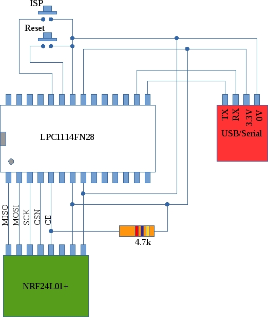
The LPC1114 hardware Interface is shown below. The MCU is connected to the NRF using 5 wires. Pin 5 of the MCU
must be pulled up as it is an open collector output. Push buttons for Reset and ISP-mode are also shown along with
a USB/Serial converter for ISP programming. Details of how to program in ISP mode are available here.
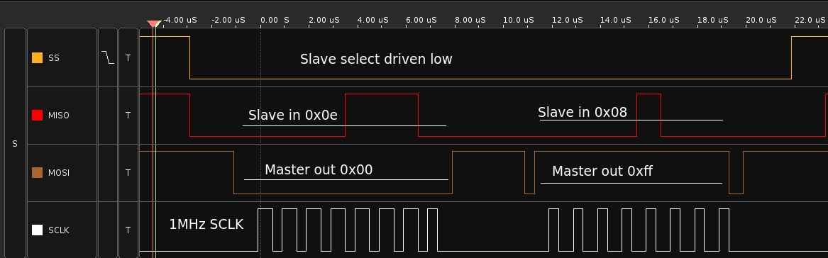
The LPC1114 is capable of generating Slave-Select signals for SPI peripherals but I found it difficult
to make it perform exactly as required. In the end, the Slave-Select (also known as CSN) and Chip Enable (CE)
controls were managed by sofware. The figure below shows the behaviour of the SPI signals during a read of
the configuration register in the NRF24L01+. When the CSN line goes low, the NRF outputs its status during the
first byte transfer (the value 0x0e). The next byte is the contents of the requested register (0x08).
These traces were captured using a Bitscope Micro USB logic analyser.
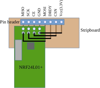
One of the difficulties with the NRF24L01+ modules is that the use a double row header to connect to the outside
world. This makes them difficult to use with a breadboard. In the case of this project, a little adapter was
made using a piece of stripboard as shown below
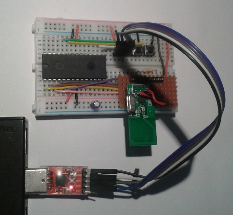
Below is a photo of the assembled and working board.
Galileo Gen2 Interface
The Intel Galileo 2 is fitted with Arduino compatible headers. The NRF24L01 radio module was interfaced by plugging
wires directly into these headers and then into the NRF module. The wiring diagram is as follows
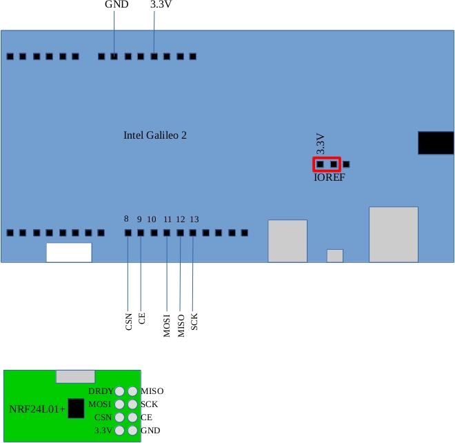
VERY IMPORTANT: Switch the I/O voltage to 3.3 volts by moving the IOREF jumper as shown
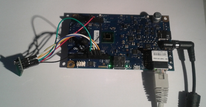
A photo of the assembled board is shown below
LPC1114 software operation
int main()
{

	uint8_t payload[10];

	int index;
	initUART();
	NRFinit();
	enable_interrupts();
	printRegisters();
	NRFWriteData(sizeof(payload),payload);
	delay(1000000);
	NRFWriteCE(1);
	printRegisters();
	payload[0]=0;
	while(1)
	{
		NRFFlushTX();
		NRFFlushRX();
		payload[0]++;
		NRFWriteData(sizeof(payload),payload);
		delay(100000);
		NRFEnableRXMode();
		// check status register to see if there is data
		if ((NRFReadRegister(7) & 0x40))
		{
			printString("Got Data ");
			NRFReadData(sizeof(payload),payload);
			printInteger(payload[1]);
			printString("\r\n");
		}
	}
}
The main function for the LPC1114 code is shown above. The program consists of a number of files:
main.cstrong> : Contains the main program code
serial.c: UART routines for communicating with the host PC
nrf24l01.c : Library routines for the NRF24L01
spi.c: Low level functions for the SPI interface
init.c: startup code for the program and interrupt vectors
The program begins by initializing the UART and the NRF24L01 (and consequently the SPI0 interface).
The printRegisters function outputs the contents of the NRF24L01 registers to the host PC
which is very useful for debugging.
The main program loop sends a 10 byte payload to the target NRF module. The first byte of this payload
is an increasing 8 bit value. The main loop then checks to see if a packet has been received, and if so,
it prints the second byte from the payload (the other device involved in the conversation puts something
in here).
Galileo software operation
The javascipt (node.js) code that runs on the Galileo is shown below. It is much the same as the C example. The
poll runs every 50ms and checks for new data. If there is new data then a reply is sent back
to the other communicating party with the second byte set equal to the bitwise inverse of the first.
/* The main body of the program follows.
 * The NRF is initialized with correct addresses etc and is periodically
 * polled to see if there is any data available in the RX FIFO
 * If there is data it is read and a reply is sent back
*/
function poll()
{
	// check to see if there is any received data
	if ((NRFReadRegister(0x7) & 0x40) > 0)
	{
		// Got data!
		console.log("Got data");
		var RXData = new Buffer(10);
		NRFReadData(10,RXData);
		console.log(RXData);
		NRFWriteRegister(0x07,0x70); // clear status flags
		RXData[1]=~RXData[0];	// send back some 'dummy' data
		NRFWriteData(10,RXData);

	}
	setTimeout(poll,50);
}

NRFinit();
NRFSetRXAddress0(5,DESTINATION_ADDRESS); // set auto ack address = destination
NRFSetTXAddress(5,DESTINATION_ADDRESS);	 // set destination address
NRFSetRXAddress1(5,SOURCE_ADDRESS);		 // set source address
console.log("Switching to RX mode");
NRFFlushTX();
NRFFlushRX();
NRFEnableRXMode();
NRFWriteCE(1);
printRegisters();
poll();
Software Operation
The figure below shows the output from node.js (the left hand panel) and the LPC1114 uart (right hand side)
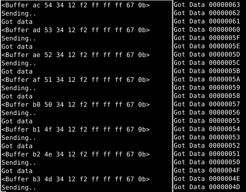
The Galileo code outputs the full contents of the buffer while the LPC1114 code outputs just the second byte
that was generated by the Galileo.
Downloads and links
The Galileo code is in a file call nrf24l01.js and is included along with the LPC1114 C code here
The Galileo was configured to run on the IOTDK (Internet of Things Development Kit) which was obtained from http://iotdk.intel.com/
If you have any questions mail me at frank.duignan@dit.ie