DT009 Year 3
Control and Automation
Minor
Revision Worksheet
Answers
1. Open loop - simple, inexpensive. Result of output not measured. Good knowledge of system required.
Think of a toaster, or electric bar heater, or maybe your electric shower at home.
Block diagram: as below except feedback loop is missing.
Closed loop - more complicated but better. Output is measured and compared against setpoint to give an error.
Suitable example – temperature control of a fridge.
Block diagram:
2. Proportional gain = constant by which error is multiplied to give the output
Proportional offset – P control must have an error to have an output, therefore, for a constant load, the PV is never equal to the SP, the amount by which it is different is Proportional offset
Increasing the proportional gain increases the output and reduces the offset
System becomes unstable
3. Integral control = error is integrated over time to give output
![]()
Used to remove proportional offset
4. Ultimate cycle - set controller to P control only; increase gain until oscillations develop; stop increasing gain when system becomes unstable
Process reaction curve - place controller in manual mode; set output to a constant value and allow system to reach a steady state; make a step change in the output and record the process variable response with time
Disadvantage of ultimate cycle is that operates on the borderline of instability - this could cause damage to plant and/or personnel
5. Step 1 is Self Test – check for errors in hardware/software
Step 2 is Input Scan – Reads input values from input cards to the memory
Step 3 is Execute Logic – each ladder in program is executed and outputs are updated
Step 4 is Output Scan – Writes output values from memory to output cards
6. (a) Types of pushbuttons: Start is normally open or press to close switch – done this way so that if wire breaks motor can’t start. Stop is normally closed or press to open switch – done this way so that if wire breaks the motor stops (it’s the same as pressing stop button).
Ladder logic – two ways of doing this.
Option 1 is as follows:
Option 2:
(b) Tank level control with switches:
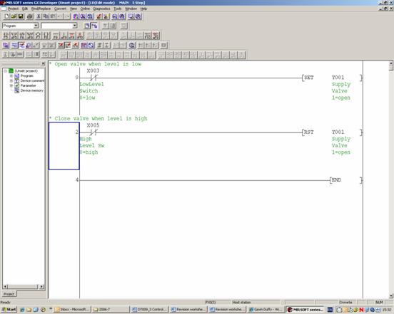
The low level switch is normally open because when it is de-energised (no water) it gives a digital input of 0. The high level switch is normally closed because when it is de-energised (no water) it gives a digital input of 1.
7.
(ii) Noise is reduced by using the averaged value from the card instead of the present value. If the averaged value is already being used and noise is still observed then increase the number of averages to further reduce the noise.
This requires changing the buffer memory address to read the data from the averaged value and also requires sending down a number of averages to the buffer memory address for this information.
(iii) Shield is a metal foil covering wire to prevent electrostatic coupling or electric field effects and is grounded at one point only.
Twisting is to prevent inductive coupling due to magnetic field effects. Voltages are still induced but in opposite directions.
(iv) Current is less susceptible to interference than voltage. Also, voltage will drop over a distance whereas current does not. Offset of 4mA is for safety – we know when the wire has broken.
8. Convert the system into a single block to give the following:
the overall output over input = transfer function

Rearrange into first order shape as follows (i.e. constant divided by (1 +s times a constant)):

The numerator (above the line) is the static gain and the time constant is the constant in the s term, i.e. = τ/(1+KpK).
9. Explain operation - Looking for: Signal into Kp = Error signal = Setpoint - Process Variable
If you are far away from the desired output level, error is large so process is driven ‘hard’. As you approach desired operating point, system is driven more and more gently.
Illustrative example: e.g. temp control of a room or of a water tank where controller is proportional (i.e. multiplies error by gain).
Reduce to one block with
transfer function = ![]()
qo can only approach qi if kp approaches infinity
Answer = ((10x0.8)/(1 + 2x10x0.8))x10 = 4.706
Yes. A high gain may result in overshoot and undershoot oscillations which may not die off. This causes instability.
10. (i) Convert the system into a single block to give the equation below:
the overall output over input = transfer function
the static gain is above the line
the time constant is constant in the s term
(ii)

Kp = proportional gain which is to be determined
K = static gain of process = 5 (given in question)

At steady state we have:

Therefore, the error is 10% of the input.
11. (i) Convert to frequency domain as follows:
![]()
Applying the
![]()
The transfer function which is the output over the input is now easily determined:

(ii) We can replace the input qi(s) in the

(iii) Check the tables to find
![]()
In the above equation, b = 1/t and Ka is a constant so remains unchanged. Therefore:

(iv) t = 5sec and step change = a =100°C, therefore equation is:
![]()
After 3 time constants, t = 15sec, therefore:

12. (i) Convert to frequency domain as follows:
![]()
Applying the
![]()
The transfer function which is the output over the input is now easily determined:

(ii) We can replace the input TJ(s) in the Laplace transformed equation above with a/s, the

(iii) Check the tables to find
![]()
In the above equation, a = 1/t. Therefore:
(iv) t = 5sec and step change = a =100°C, therefore equation is:
![]()
After 3 time constants, t = 15sec, therefore:
13. (i) Block Diagram

(ii) On-Off control is suitable because the tank has a large capacity so its temperature changes slowly. The temperature does not have to be accurately maintained. It is simple to implement.
(iii) Add a deadband or hysteresis.
(iv)
14. (i) Convert to frequency domain as follows:
![]()
Applying the
![]()
The transfer function which is the output over the input is now easily determined:
(ii) We can replace the input TJ(s) in the Laplace transformed equation above with1/s2, the

(iii) Check the tables to find

In the above equation, a = 1/t. Therefore:

(iv) t = 40sec and ramp =1°C/second, therefore equation is:

Sketch should look like:

After 240 seconds, t = 240sec, therefore:

i.e. lagging the jacket by a temperature equivalent to the time constant in ºC.
15. A proportional plus integral plus derivative controller is usually referred to as a three term controller. Equation is:

The proportional term acts in proportion to the error. It acts on the present state of the error.
The integral term eliminates the proportional offset or steady state error. It acts on the past history of the error.
The derivative mode reduces the tendency towards oscillations and provides a control action which anticipates changes in the error signal. The derivative mode is useful if the process has sudden load changes. It anticipates the future direction of the error.